Related work
A new generation of the Baby-QRO switching amplifier targets 25W to 50W of RF
output for FT8 and other FSK modes.
Goal
The Baby-QRO amplifier already has a very useful RF power control knob: the PA drain voltage. A bench supply works for experiments, but it is not the right answer for a digital beacon or transmitter stack. We want the MCU controller to set the PA voltage, and therefore the RF output power, in software.
Supply choice
The ideal supply for this job is boring:
- Accepts common 12V / 24V field supply inputs
- Produces the 25V to 50V range needed by the PA
- Is cheap and widely available
- Is easy to replace if we break one
- Can be modified with normal lab tools
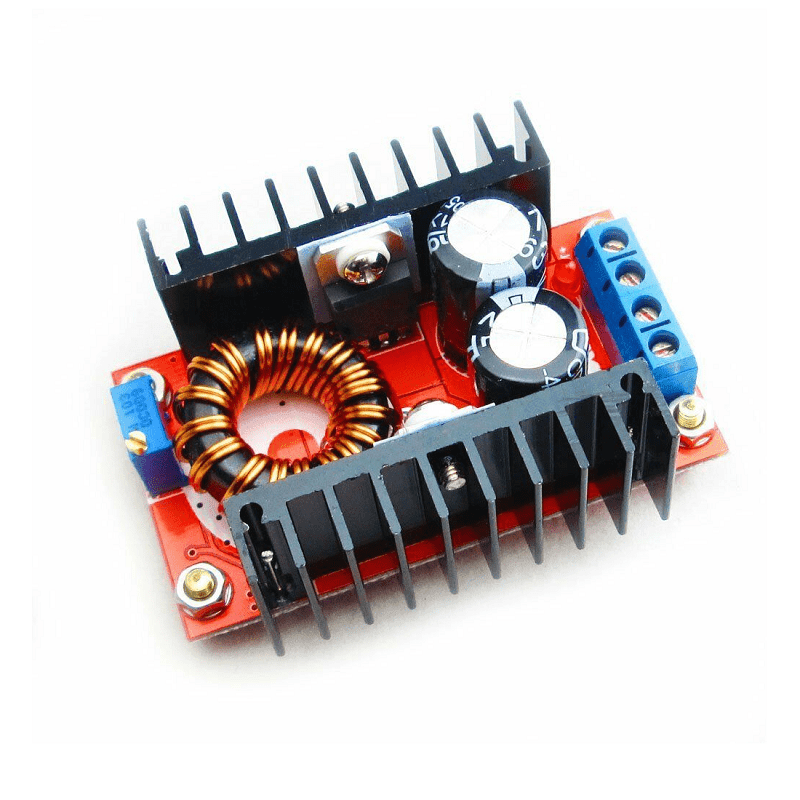
After considering a custom boost converter, we settled on modifying the widely
available 120W 12-32V to 35-60V 6A DC-DC Boost Converter Module.
This module is not perfect. It is attractive because it is inexpensive, available from many sellers, and already handles the high-current switching layout well enough for experiments.
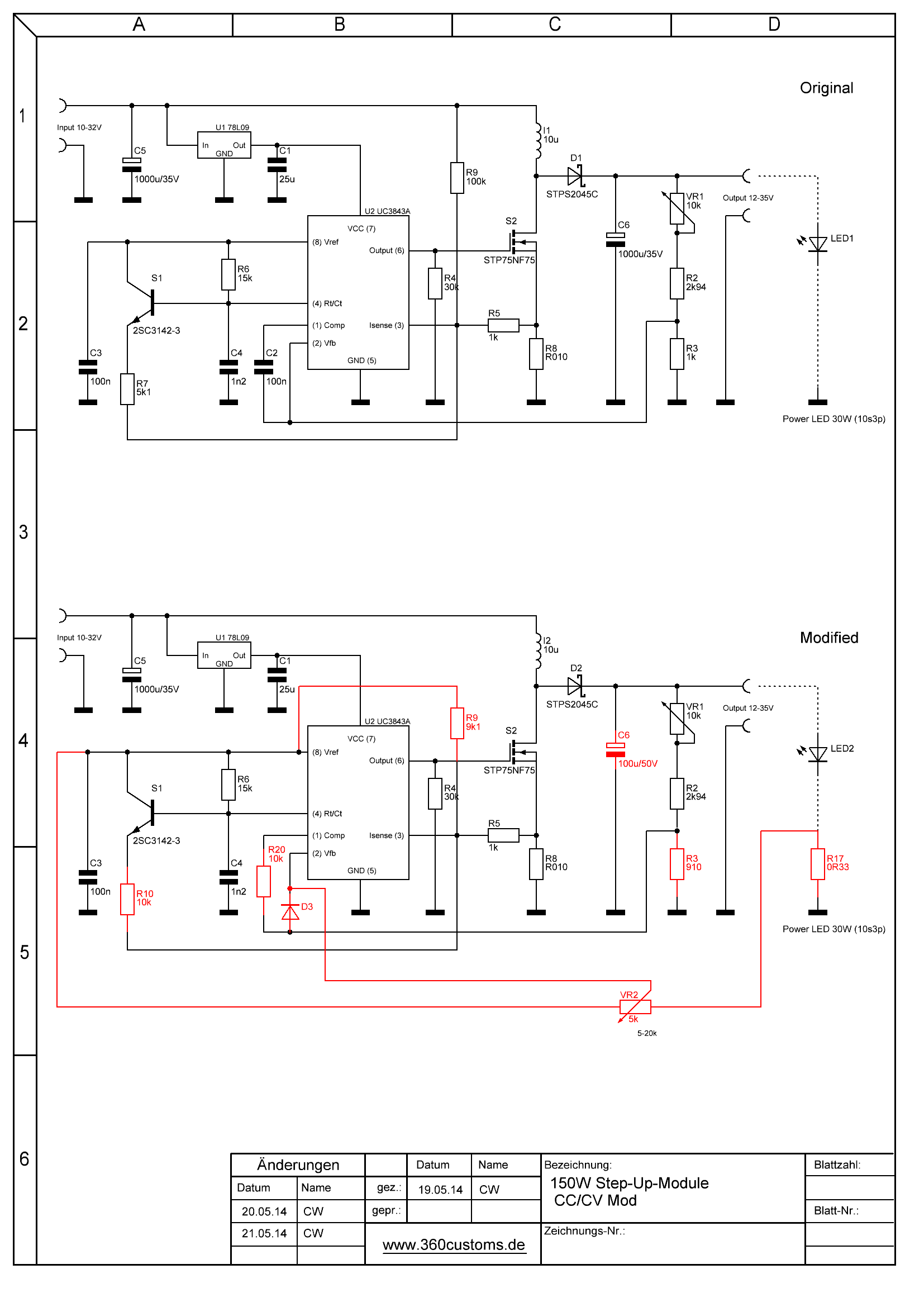
Schematics for a closely related boost module:
Digital adjustment
The plan is to leave the boost converter power stage alone and only take over the voltage adjustment path.
This can be done by injecting a MCU-controlled voltage at the FB point.
For initial testing:
VOUT+  o----[ upper feedback / trim network ]----o----[ lower feedback ]----GND
                                                |
                                                +---- FB pin of boost IC
                                                |
MCU 3.3V control o------------[ 1k ]------------+
By doing the above, we were able to reduce the voltage from 40V to ~28V.
The FB point to tap can be found easily using a multimeter near the resistors - this
point will have ~2.4V on it. The GND point can be tapped from the large
ceramic capacitor on the PCB. As a reference, the pin 5 of the active IC is
GND.
Later on:
GPIO15 PWM
    |
   470R
    |
    +---- 1uF ---- GND
    |
   1k
    |
   FB
RPi Pico MCU Code
const int PWM_PIN = 15;

void setup() {
  analogWriteFreq(100000);  // 100 kHz
  analogWriteRange(1023);   // 10-bit

  // Set power level here:
  analogWrite(PWM_PIN, 512);
}

void loop() {
}
analogWrite(PWM_PIN, 0);      // Maximum voltage (~50V)
analogWrite(PWM_PIN, 256);    // High power
analogWrite(PWM_PIN, 512);    // Medium power
analogWrite(PWM_PIN, 768);    // Low power
analogWrite(PWM_PIN, 1023);   // Minimum voltage (~28-30V)
PA power control
For the Baby-QRO amplifier, changing the drain supply voltage is a clean way to control RF output power. It avoids depending entirely on RF drive reduction and allows simple firmware presets such as low, medium, and high power.
This also makes automated testing easier: sweep the supply voltage, measure RF output, and build a calibration table.
Why this route
A custom digitally controlled boost converter would be nicer on paper. In this project, the module route wins because it is cheap, available, replaceable, and good enough to move the RF work forward.
That is the useful compromise here: do the RF and firmware work ourselves, but do not reinvent a commodity boost converter unless the modified module proves to be the limiting factor.
Future work
- Test the actual stability of this module at various voltages using a DC
Electronic Load (
OWON OEL1530TV).