I wanted an ESP8266 to answer a simple question: is mains power available?
The ESP8266 was willing to help, provided nobody introduced it to 230 V.
An ordinary isolated 5 V wall adapter already gives us a useful signal: its DC output disappears when its mains supply disappears. We can watch that output and leave the mains side inside the adapter, where it belongs.
Two resistors make the voltage suitable for the development board's ADC. The slightly less obvious requirement is keeping the observer alive when the thing being observed switches off.
A power-cut detector which also dies during the power cut is a rather committed participant in the experiment.
The useful little board
The key part is an LX-2BUPS 18650 UPS module, used here with a 5 V output. Robu lists it as the 3A 18650 Lithium Battery Charger Module with Battery box 5V Type-C (SKU: R175138). The board marking is useful when searching through the many nearly identical product names.
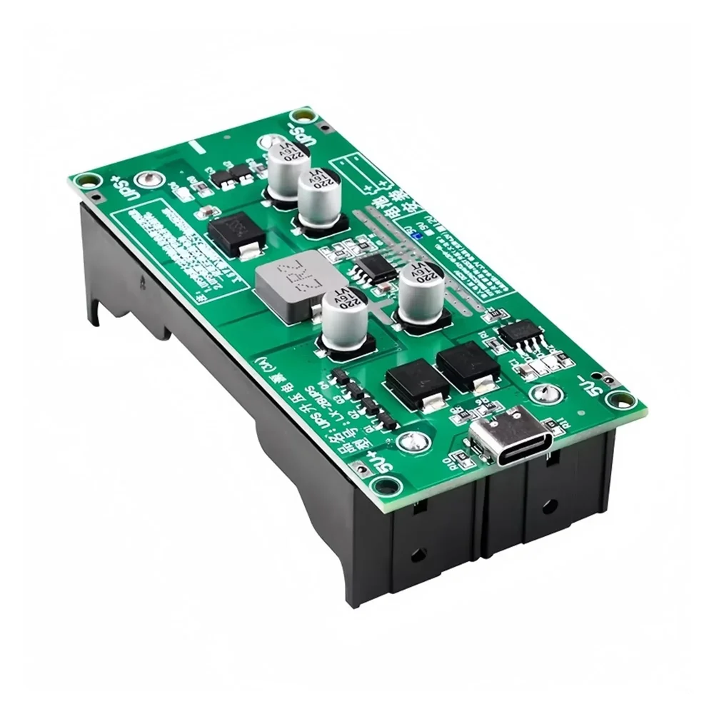
The wall wart / SMPS adapter feeds the module, the 18650 cells provide backup, and the module's 5 V output powers the ESP8266 development board. The intended result is that the ESP8266 keeps running when the adapter loses power.
Use the 5 V output version/configuration and check it before connecting the ESP8266's USB or 5 V power input; similar-looking boards carry other output-voltage options. The advertised current rating is not a measurement of this particular installation.
Measure the input, power from the output
There are two different 5 V nodes in this project:
| Node | What happens during an outage? | Job |
|---|---|---|
| Adapter output / UPS input | Falls when the adapter loses mains | Sense this |
| UPS output | Stays up while the battery can supply it | Power the ESP8266 |
The low-voltage power flow looks like this:
Isolated 5 V adapter, plugged into the mains socket being monitored
    |
    +----> resistor divider ----------------------> ESP8266 A0
    |
    +----> LX-2BUPS input
                |
          battery-backed 5 V output -------------> ESP8266 USB / 5 V input
                ^
             18650 cells in the module's holder
Connect the adapter's low-voltage ground, UPS ground, divider ground and ESP8266 ground together.
Take the sensing voltage before the UPS output. Measuring the battery-backed output would mostly tell us that the UPS is doing its job. That would be a very reliable way to miss the power cut ;)
The adapter itself must be connected to the mains supply we want to observe. Putting it on a household inverter or another UPS would make it report the availability of that backed-up supply instead.
All the added wiring is on the isolated, low-voltage side. A resistor divider connected directly to mains is a completely different circuit and provides no isolation.
Two resistors and a little patience
I am using 15 kΩ and 22 kΩ resistors with an approximately 5 V input.
For example, putting 22 kΩ between the adapter output and A0, and 15 kΩ between A0 and ground, gives an unloaded divider voltage of:
V_A0 = 5 × 15 / (22 + 15) ≈ 2.03 V
Reversing those resistors gives about 2.97 V. The board's existing ADC divider also loads this circuit, so these are approximate external-node voltages rather than a calibration certificate.
Check the ADC range of the actual board. The bare ESP8266 ADC accepts only 0–1.0 V. Some development boards add an onboard divider; for example, the LOLIN D1 mini specifies a 3.2 V maximum at A0. Neither of the external divider arrangements above is suitable for feeding a bare 1 V ADC directly.
For the development-board setup, the firmware uses these configurable raw ADC thresholds:
#define POWER_ON_THRESHOLD  450
#define POWER_OFF_THRESHOLD 250
#define DEBOUNCE_MS         100
A reading at or above 450 means present; at or below 250 means absent. Between them, the firmware holds the previous state. A candidate state must persist for 100 ms before being accepted. If the first reading is in that middle band, the state remains unknown until a threshold is crossed.
This hysteresis stops a slightly noisy voltage from turning one power cut into a Telegram conversation.
The onboard LED follows the confirmed state: on for mains present, off for mains absent, and initially off while the state is unknown. It works even without WiFi. A remarkably useful feature for something called an LED.
The reporting part
I recycled an old water-level monitoring codebase for this project. The ultrasonic sensor's UART code has retired; the payload is now:
{"power_present": false}
The ESP8266 publishes the first confirmed state, subsequent changes, and a heartbeat every 30 seconds. Failed requests retry without rebooting the board. The Flask backend stores the readings in SQLite, draws a binary history chart, and can send Telegram alerts when power is lost or restored.
The firmware and backend are on GitHub.
The configured dashboard URL is PowerSensor.pythonanywhere.com/graph.
A stale report becomes unknown / sensor offline after 90 seconds. Silence could mean a dead router, lost WiFi, or an unreachable server; it does not establish that mains has failed.
The router and any required ONT also need backup power for remote alerts. This small UPS takes care of the ESP8266 in this setup. The rest of the network still needs to survive the same event.
What the detector actually knows
It knows whether the monitored adapter is producing enough voltage to cross our thresholds. An unplugged adapter, a failed adapter and a genuine mains outage can all produce the same answer.
There is also some delay: an adapter's output capacitor can keep its output alive after AC is removed. Add the confirmation interval and network time. This is an availability monitor, with no claim to cycle-level timing, mains-voltage measurement or brownout analysis.
The little trick is keeping one supply alive while watching another supply disappear. The mains can keep its distance.