Note: This HF LNA design is inspired by PY2OHH designs and mcHF work.
Previous article: Single Transistor LNA for HF - it cut a corner when it came to output impedance matching ;)
Design
The idea that a single-transistor preamp with 10 dB gain is more than enough
for HF comes from Gajendra Kumar (VU2BGS). As a new "designer," I am often
overwhelmed by the available design paths, so guidance from an elmer is
crucial.
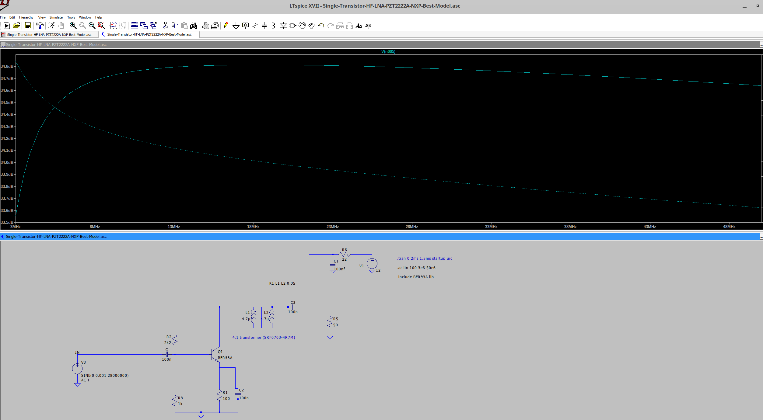
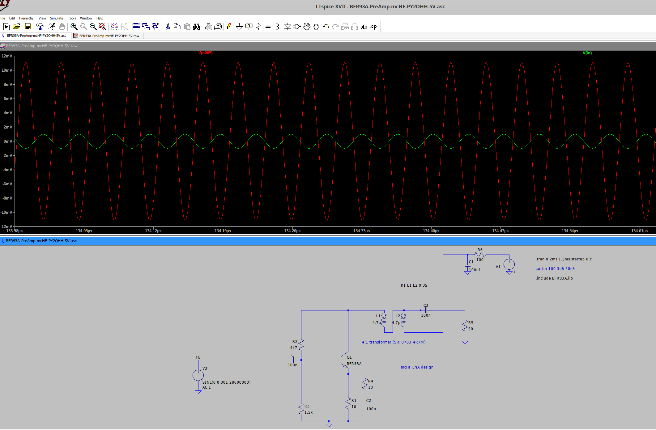
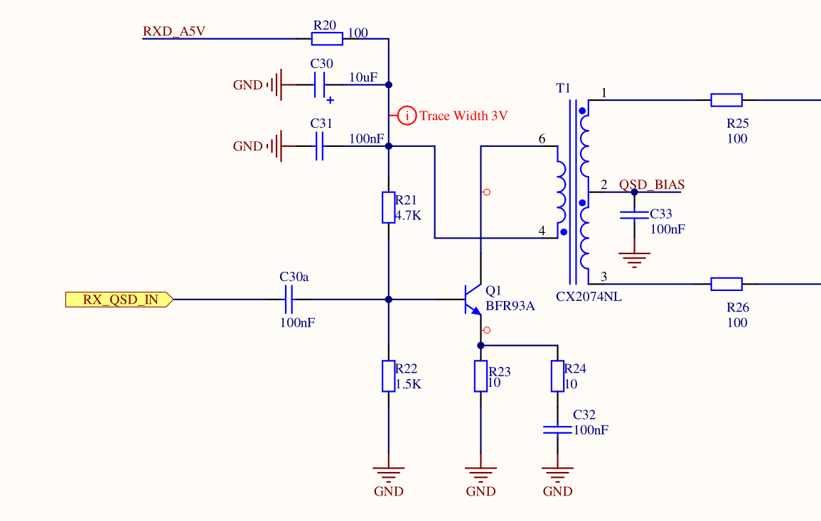
Circuit diagram (original from mcHF project):
Implementation
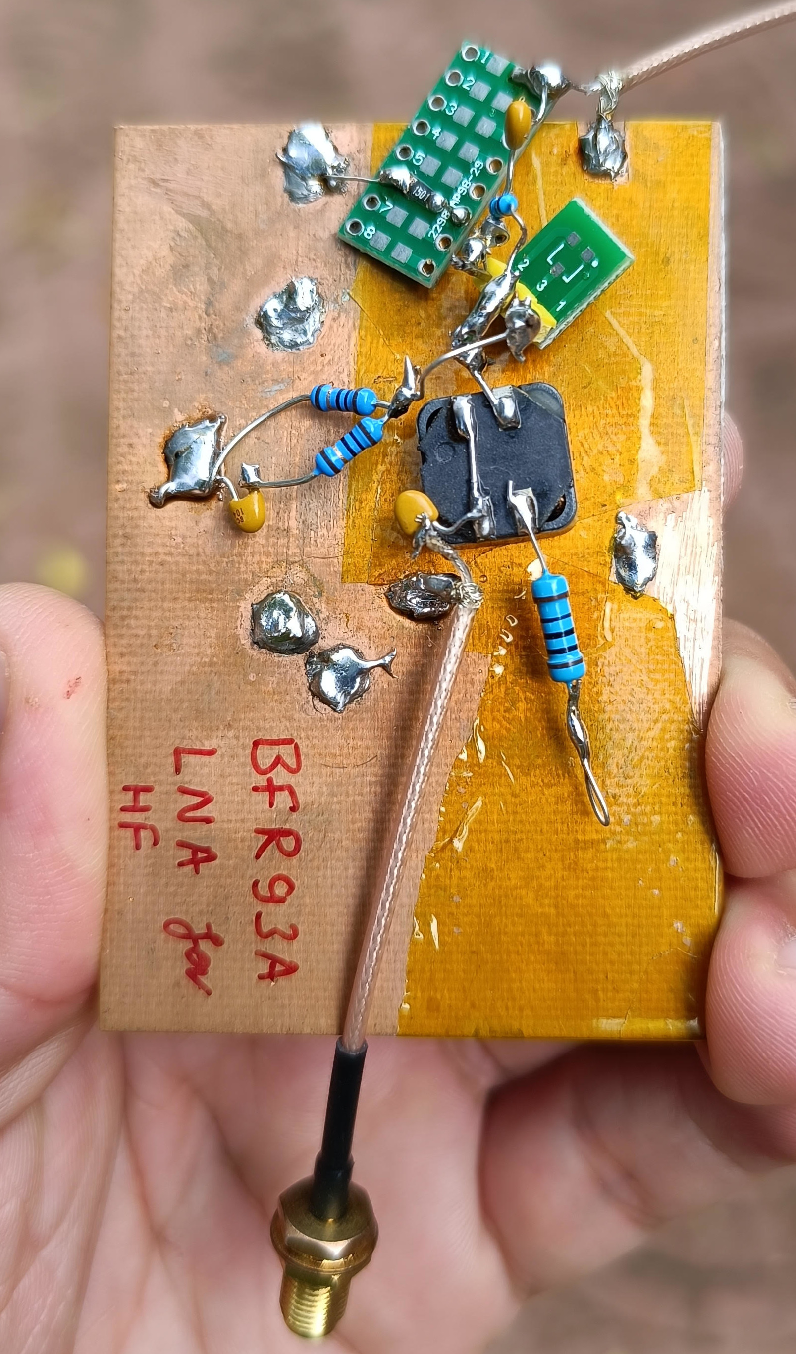
Actual quick build:
This properly impedance matched LNA will be used in the RX path of the DDX Commercial series of transceivers soon. It can also perhaps replace the 2N3906 RF AMP (https://www.n6qw.com/MC1496.html) for usage with MC1496 based DCRs.
Note: If BRF93A oscillates (its 6 GHz fT is excessive for our needs) in the PCB build version, then we can try our luck with S9018 or MMBTH10LT1G transistors (same pinout).
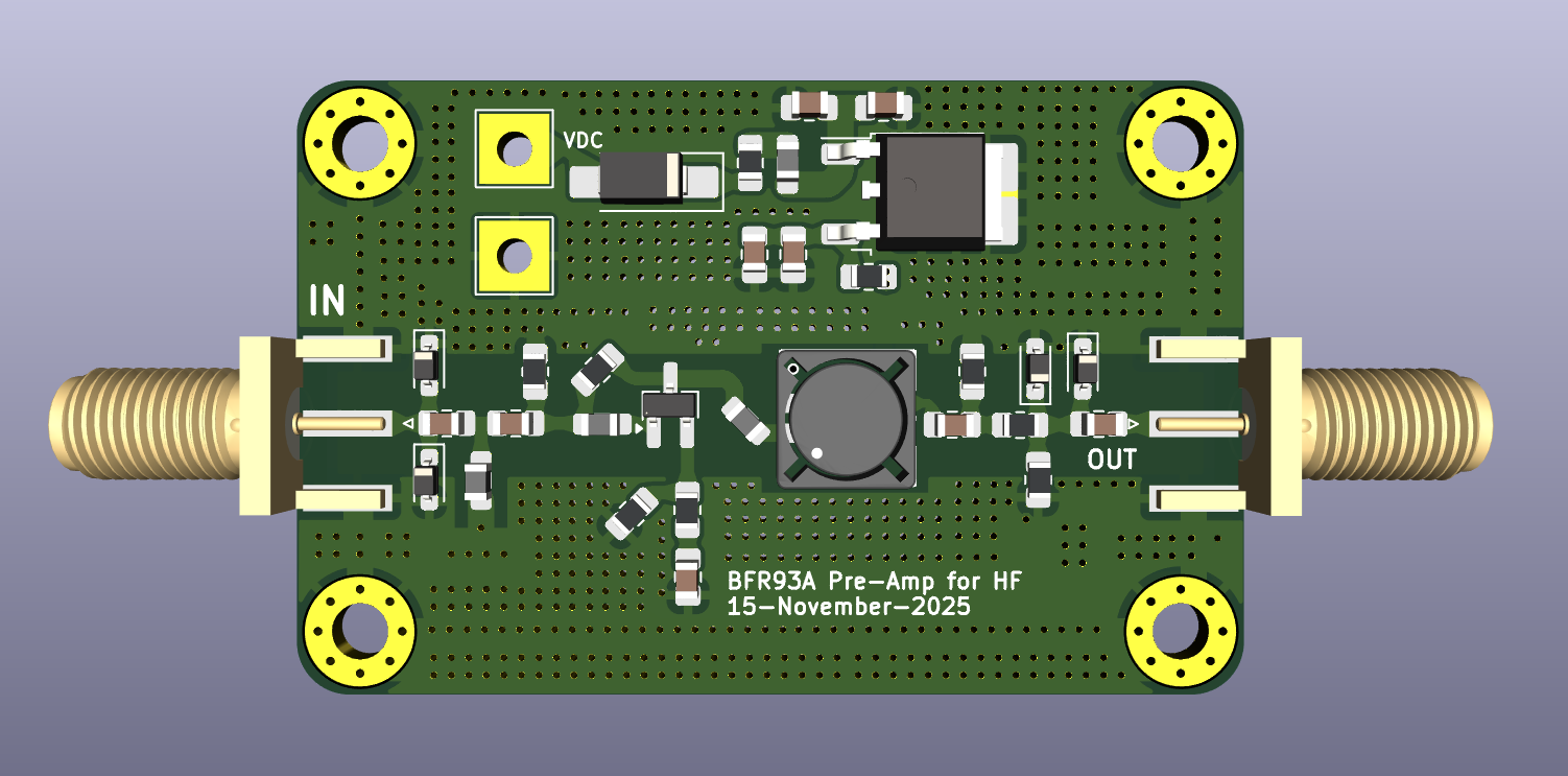
Our twist: We found that there is NO need to wind and build the 4:1 transformer by hand. Instead, we can simply use a SMD coupled inductor from LCSC in the compact SMD-4P,7.5x7.5mm footprint.
PCB render:
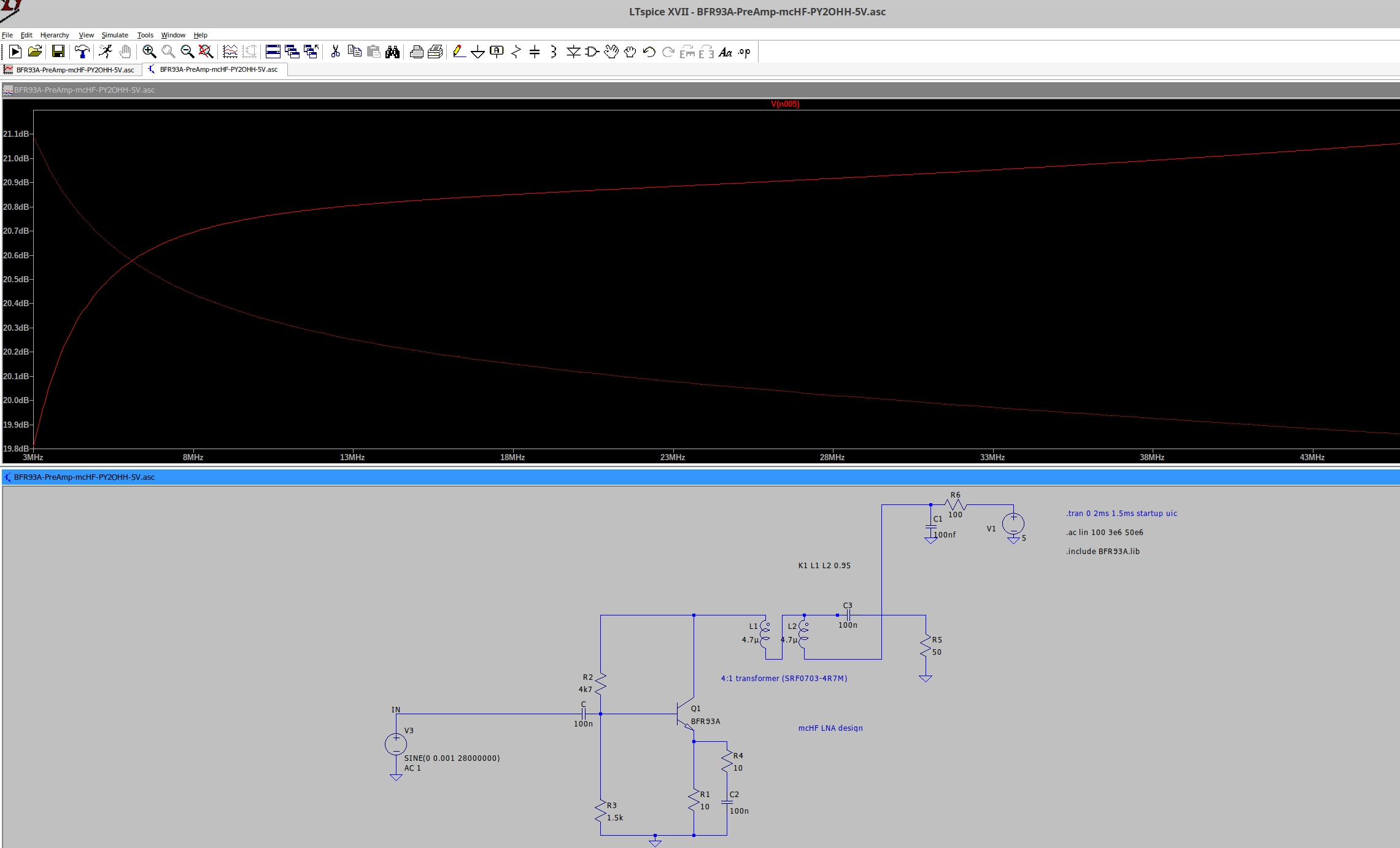
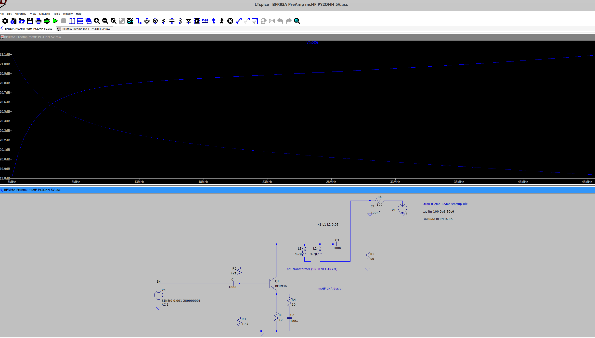
Results
NanoVNA results:
- Input ATTN: 10dB (Port 1 of NanoVNA)
- Output ATTN: 50dB (Port 2 of NanoVNA)
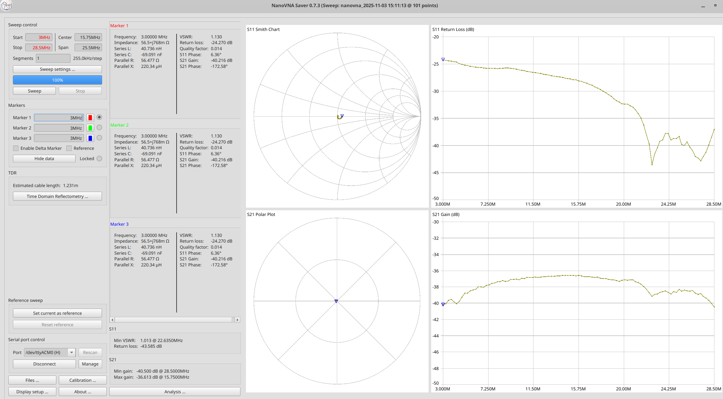
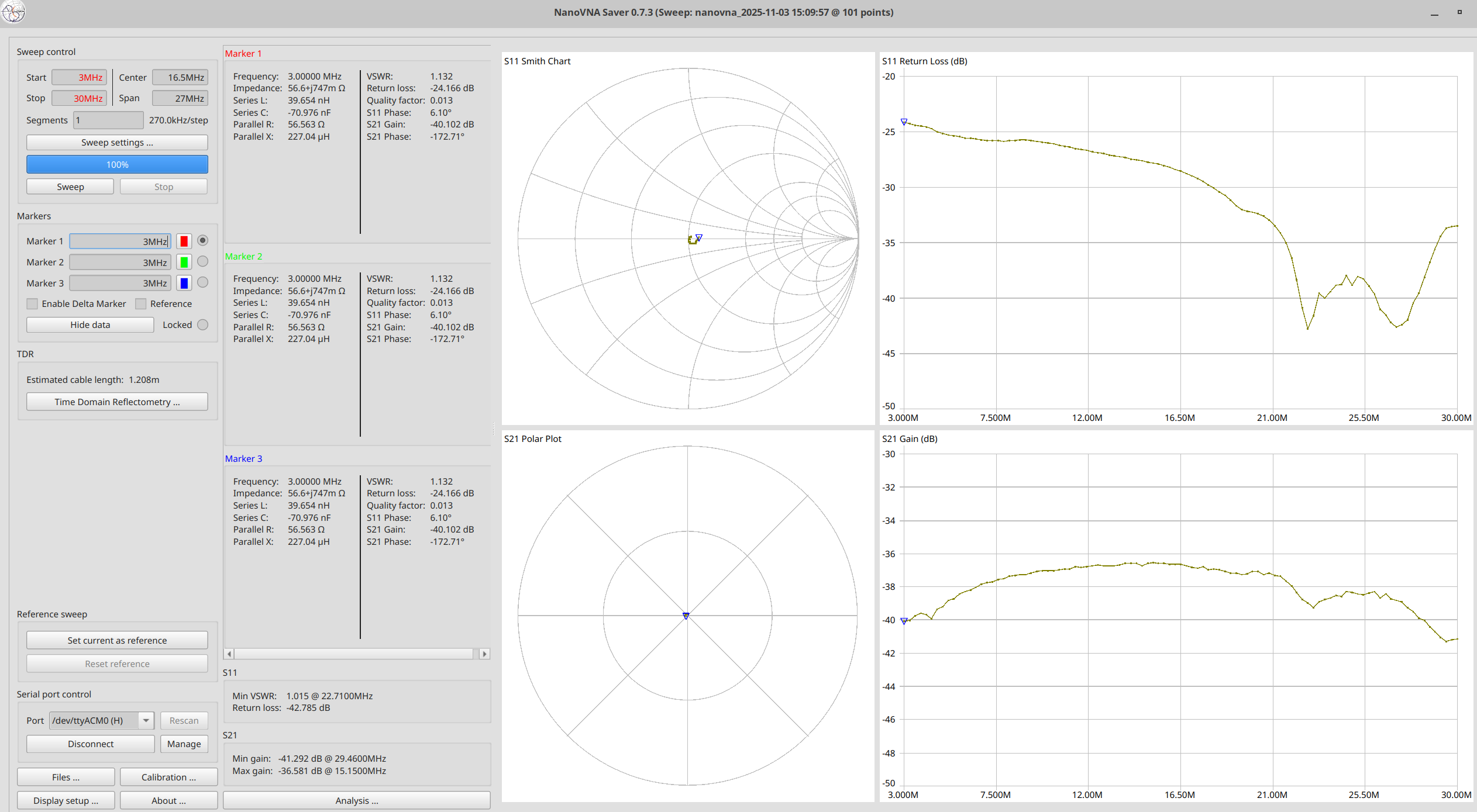
Resulting gain: ~20dB or more over HF
Power consumption: ~9mA @ 5V
WSJT-X results:
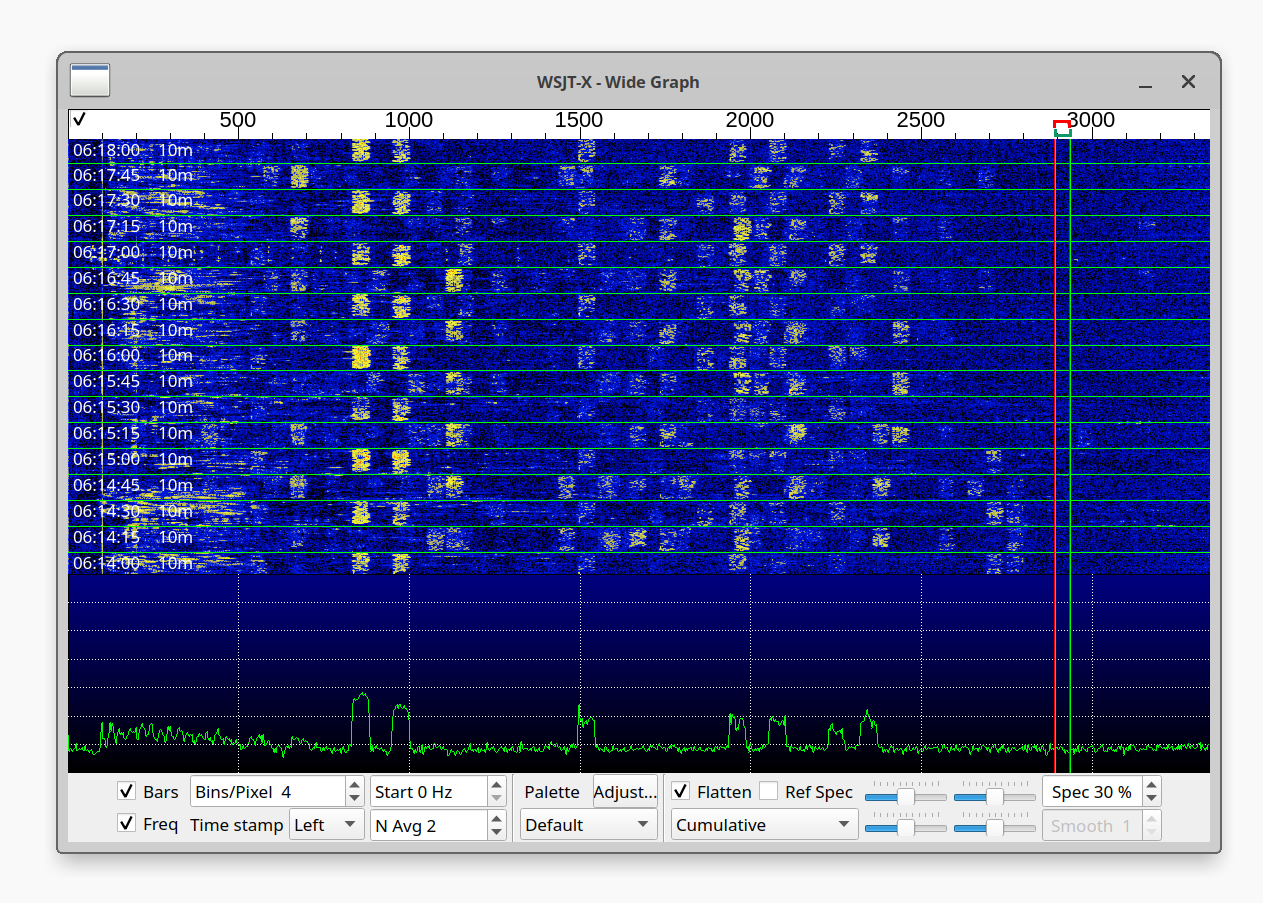
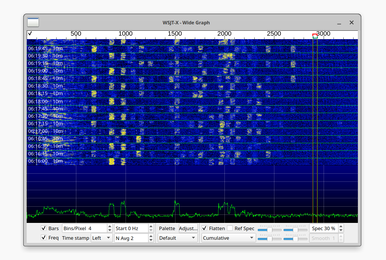
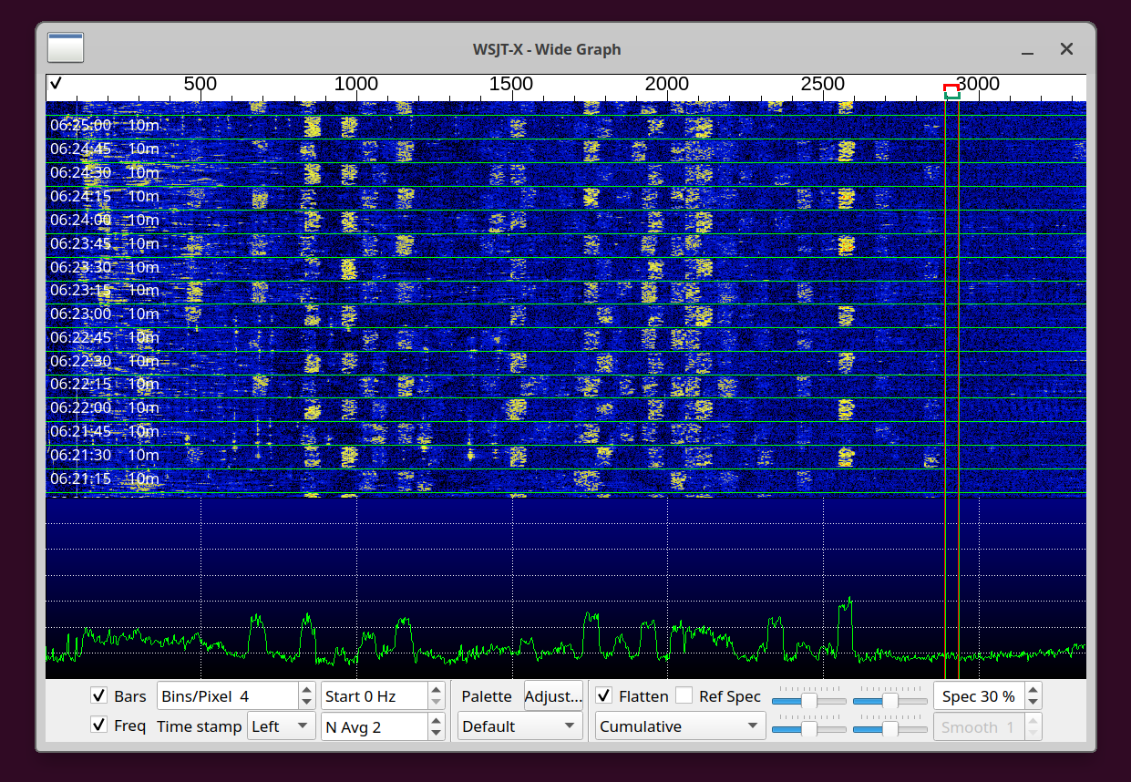
Even the partially-overlapping signals are decoded just fine in WSJT-X!