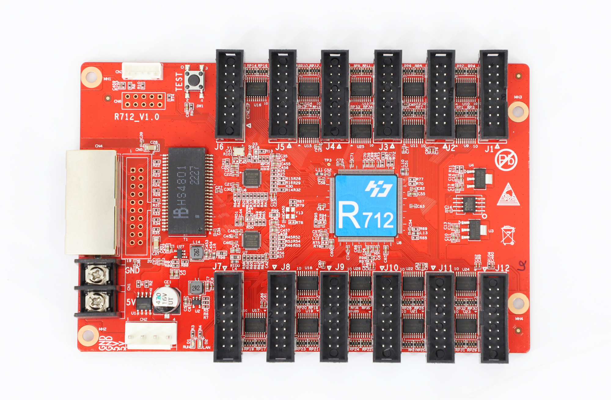
We are working on reversing the Huidu HD-R712 LED Display Full Color Receiving Card - a very cost-effective (~1000 INR) and widely available FPGA board.
We draw inspiration from the https://github.com/q3k/chubby75 work.
Random brain dump
$ sudo openFPGALoader --cable dirtyJtag --freq 10000 --detect
Jtag frequency : requested 10000Hz -> real 10000Hz
index 0:
	idcode 0x4014c35
	manufacturer anlogic
	family eagle d20
	model  EG4D20EG176
	irlength 8

$ sudo openFPGALoader --cable dirtyJtag --detect
Jtag frequency : requested 6000000Hz -> real 6000000Hz
index 0:
	idcode 0x4014c35
	manufacturer anlogic
	family eagle d20
	model  EG4D20EG176
	irlength 8
JTAG pinout:

                  V
┌───────────────────┐
│ 1   3   5   7   9 │
│ 2   4   6   8  10 │
└───────────────────┘

9 => TCK

7 => TDO

5 => TMS

3 => NC (Not Connected)

1 => TDI
The pin mapping work was done using a DMM, the datasheet, and an optical magnifier.
We could NOT get https://github.com/Aodrulez/blueTag to work - we spent a few
hours trying to repair the program but no luck either. We then shifted to
https://github.com/cyphunk/JTAGenum and got a working RPi Pico port
(https://github.com/kholia/JTAGonaut) in less than 15 minutes!
$ make flash
sudo openFPGALoader --cable dirtyJtag -v led.bit
Jtag frequency : requested 6000000Hz -> real 6000000Hz
found 1 devices
index 0:
	idcode 0x4014c35
	manufacturer anlogic
	family eagle d20
	model  EG4D20EG176
	irlength 8
File type : bit
Parse file header end
DONE
bitstream header infos
Architecture: eagle_s20
Bitstream CRC: 1110011001000011
Date: 2026/ 2/27  8: 7
Design name: led
Package: BG256
USER CODE: 00000000000000000000000000000000
Version: 5.0.28716
tool: Anlogic Infotech Corporation ASCII Bitstream
Loading: [==================================================] 100.00%
Done
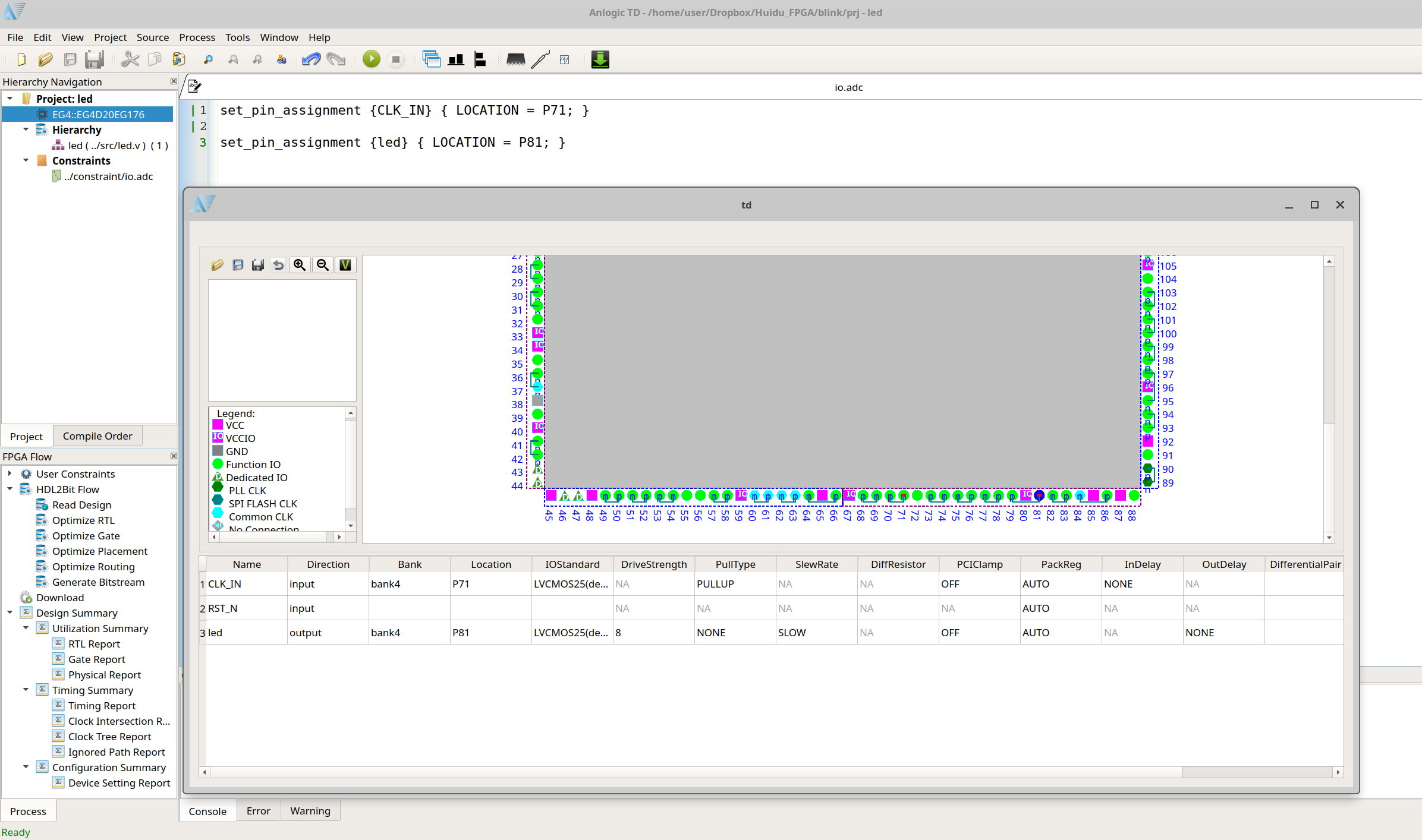
Basic IO constraints details
set_pin_assignment {CLK_IN} { LOCATION = P62; }

set_pin_assignment {led} { LOCATION = P81; }

set_pin_assignment {rf_out} { LOCATION = P49; }

# This is the 'key+' header pin
set_pin_assignment {uart_rx} { LOCATION = P42; }

# J7 - last pin
set_pin_assignment {rf_out} { LOCATION = P98; }

# Enable output buffers
set_pin_assignment {oe} { LOCATION = P8; }
This is enough to get the LED and one-directional UART working!
Sample Verilog Code
This Verilog code blinks the LED on UART activity:
module top (
    input  wire CLK_IN,    // 25 MHz clock
    input  wire uart_rx,   // UART RX (idle high)
    output wire led        // active-low LED
);

    // ============================================================
    // Parameters
    // ============================================================

    localparam CLK_FREQ      = 25_000_000;
    localparam BAUD          = 115200;
    localparam CLKS_PER_BIT  = CLK_FREQ / BAUD;     // ~217
    localparam FLASH_TIME    = 25_000_000 / 20;     // 50ms flash

    // ============================================================
    // UART Receiver (8N1)
    // ============================================================

    reg [15:0] baud_cnt   = 0;
    reg [3:0]  bit_idx    = 0;
    reg [9:0]  shift_reg  = 10'b1111111111;
    reg        receiving  = 0;
    reg        byte_valid = 0;

    always @(posedge CLK_IN) begin
        byte_valid <= 0;

        // Detect start bit (falling edge)
        if (!receiving && uart_rx == 0) begin
            receiving <= 1;
            baud_cnt  <= CLKS_PER_BIT / 2;  // sample mid-bit
            bit_idx   <= 0;
        end

        if (receiving) begin
            if (baud_cnt == 0) begin
                baud_cnt <= CLKS_PER_BIT - 1;

                shift_reg <= {uart_rx, shift_reg[9:1]};
                bit_idx   <= bit_idx + 1;

                // After 1 start + 8 data + 1 stop = 10 bits
                if (bit_idx == 9) begin
                    receiving  <= 0;
                    byte_valid <= 1;  // pulse when byte done
                end
            end else begin
                baud_cnt <= baud_cnt - 1;
            end
        end
    end

    // ============================================================
    // LED Flash Logic (short pulse per byte)
    // ============================================================

    reg [31:0] flash_counter = 0;
    reg        flash_active  = 0;

    always @(posedge CLK_IN) begin
        if (byte_valid) begin
            flash_active  <= 1;
            flash_counter <= FLASH_TIME;
        end
        else if (flash_active) begin
            if (flash_counter == 0)
                flash_active <= 0;
            else
                flash_counter <= flash_counter - 1;
        end
    end

    // Active-low LED
    assign led = flash_active ? 1'b0 : 1'b1;

endmodule
$ pyserial-miniterm /dev/ttyACM0 115200
--- Miniterm on /dev/ttyACM0  115200,8,N,1 ---
--- Quit: Ctrl+] | Menu: Ctrl+T | Help: Ctrl+T followed by Ctrl+H ---
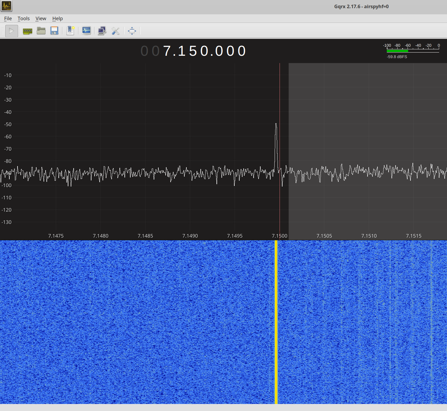
Sample RF carrier generation program:
module top (
    input  wire CLK_IN,   // 25 MHz clock
    output reg  rf_out,
    output wire  oe
);

    // NCO phase accumulator
    reg [31:0] phase_acc = 0;

    // Always enabled (active-low)
    assign oe = 1'b0;

    // 7.150 MHz at 25 MHz clock
    localparam [31:0] CARRIER = 32'd1228365855;

    always @(posedge CLK_IN) begin
        phase_acc <= phase_acc + CARRIER;
        rf_out    <= phase_acc[31];   // MSB = square wave
    end

endmodule
English Datasheet
Next Steps
I just need to map one more pin for the bi-directional high-speed UART comms to call this work 'usable'.
References and Credits
https://dl.sipeed.com/shareURL/TANG/Primer/IDE (FPGA 'toolchain')
https://github.com/q3k/chubby75/issues/123 (initial forays…)
https://github.com/kholia/Colorlight-5A-75B/tree/master/dds_ssb_uart_alt
https://trabucayre.github.io/openFPGALoader/vendors/anlogic.html#anlogic
https://github.com/mmicko/prjtang (not used yet but we want to)
https://github.com/kholia/JTAGonaut - Port of https://github.com/cyphunk/JTAGenum to RPi Pico